High-Speed Connectors Simulation
Introduction
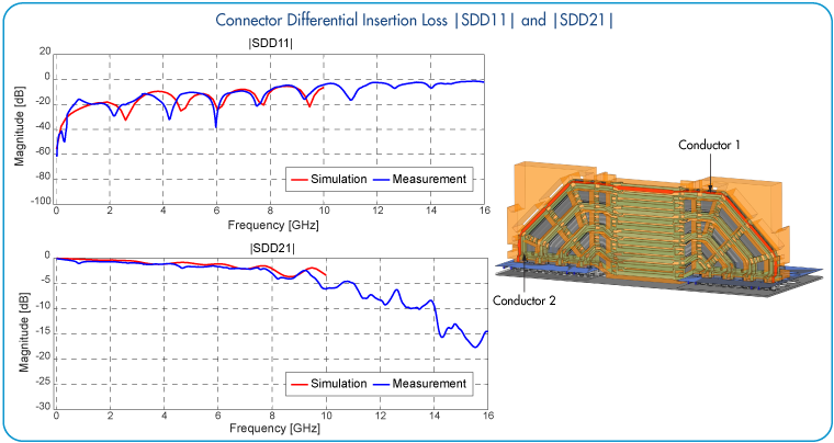
The high-speed connectors are commonly used in multi-boards to transmit signals between PCBs. Investigation of their characteristics plays important role in signal integrity and channel analysis of a system. This application note demonstrates modeling and 3D full wave simulations of a high-speed differential connector in EMCoS Studio environment. Simulated characteristics of the connector are compared with reference measurement data provided by Missouri S&T EMC Laboratory.

Simulation Model Description
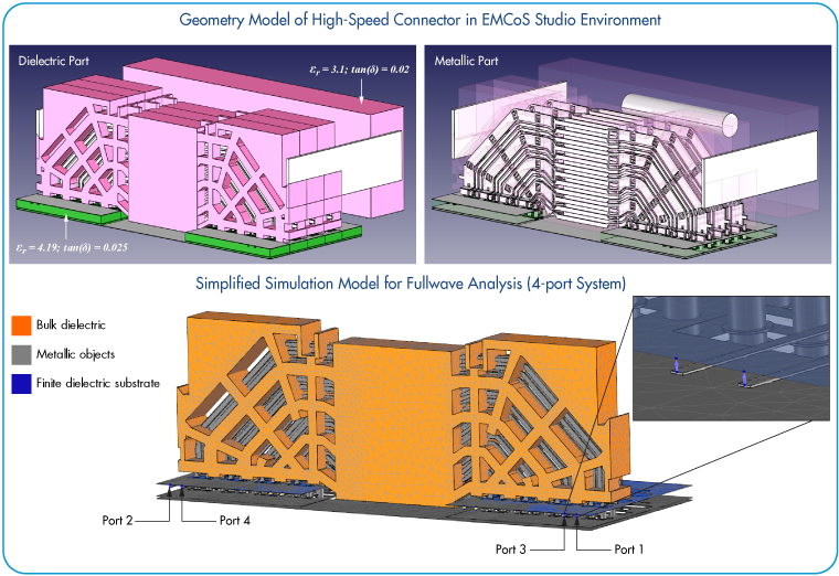
The original geometry model of a high-speed connector was imported from CAD file format. In order to simplify the model construction and reduce simulation time for full wave analysis, only one connector wafer was considered with assigned 4-ports for S-parameters calculation. The relative permittivity and the loss tangent of connector plastic material were assigned to be 3.1 and 0.02 correspondingly. The PCB board was modelled with relative permittivity 4.19 and loss tangent 0.025. All conductors in the model were assigned to be perfect electric conductors.

Comparison of Simulation and Measurement Results
Comparison of simulation and measurement results for high-speed connector is presented below:


Application note was prepared in cooperation with Missouri S&T EMC Laboratory

