LFEF Simulations for PCB with Terminal Blocks Conversion Adapter
Introduction
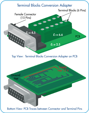
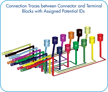
This application note demonstrates capacitance matrix calculation for PCB with conversion adapter between DB15 female connector and 6-pin terminal blocks using Low Frequency Electric Field (LFEF) solver.
The modelling approaches are the following:
- Geometry models of PCB and terminal blocks adapter can be constructed using EMC Studio CAD tools or imported from NASTRAN or CAD formats
- Dielectric materials with different permittivity values are used for PCB and terminal blocks modelling (PCB: ε – 2.5; connector: ε – 4.5; terminal blocks: ε – 6.6)
- PCB dimensions are the following: 77 mm x 68 mm x 1.8 mm; trace width is 1 mm
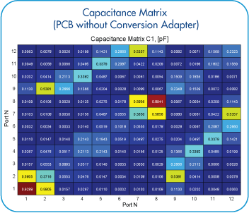
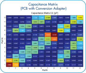
- Two calculation models are considered. On the first step capacitance matrix is calculated for PCB traces without conversion adapter. Next calculation of full model with terminal blocks conversion adapter is performed. Difference between obtained capacitance matrices is demonstrated
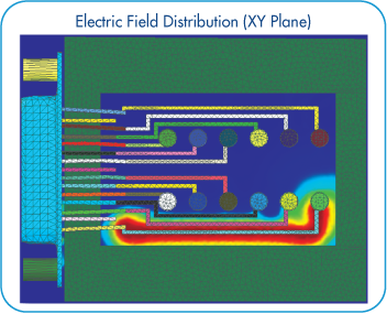
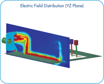
- Electric field distribution on different observation planes is visualized
Simulation Model Description
Results
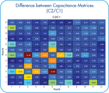
Difference between obtained capacitance matrices for PCB with and without conversion adapter is shown below:
Difference between obtained capacitance matrices for PCB with and without conversion adapter is shown below:


