EMCoS Studio 2019

Major Highlights
- Auto Merging of Electronic Circuit with 3D PEEC Equivalent Model of PCB Layout
- Advanced ODB++ Import Procedure with Improved Stackup Editor
- New Features in 3D PEEC Solution
- CM Choke Designer Based on PEEC Method
- Real Ground Support with Sommerfeld Approach
- Waveguide Ports Support
- New Transient Analysis Mode with Time Domain Integral Equation (STime_IE) Solver
- High Frequency Solution with New HF3D Solver
- New EMCoS CAD Converter for Complex Geometry Processing
- New Features and Improvements in Geometry and Model Handling Operations
- New Features and Improvements in System Simulation Analysis Type
- New Features and Improvements in EMCoS SimDAT
Auto Merging Procedure of Electronic Circuit with 3D PEEC Equivalent Model of PCB Layout
New PCB import options give possibility to extract BOM report (Bill of Material) from ODB++ file format. During importing information about all PCB components and pins is translated from ODB++ to Excel spreadsheet – an essential part of automatic merging procedure.
As a result of 3D PEEC calculation equivalent circuit of PCB layout will be automatically merged with functional scheme based on BOM data. Netlist device representing initial functional circuit can be easily substituted with complete scheme including all parasitic effects of PCB traces directly in System Diagram, preserving all the existing connections to other devices.
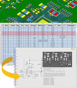
Advanced ODB++ Import Procedure
- Full control of overall process of ODB++ importing
- Support of ODB++ V8 reading and import of drills objects
- Options to exclude features outside profile and outside nets during PCB data import
- Option to ignore net $NONE$ during PCB data import
- Possibility to exclude footprints from PCB data import
- Controlling of top and bottom footprints visualization color
- Controlling of footprints offset from top and bottom layers
- Autogenerate nets option for PCB models with incomplete information about nets
Updated Stackup Editor gives possibility to configure ODB++ import options directly from Stackup Editor, where user can define as many presets as needed for different PCB configurations.
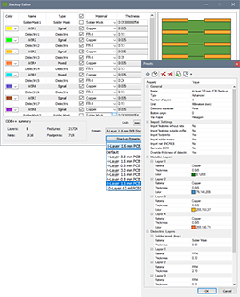
New Features and Improvements in 3D PEEC Solution
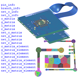
- Support of wires and multiple finite dielectric substrates
- Support of 3D PEEC model visualization and RLC matrix view for automatic partitioning calculations in EMCoS SimDAT
- Special options for C-subnets and L-subnets matrices calculation and results analysis
- 3D PEEC output reading functions support in scripting language
CM Choke Designer
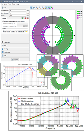
CM Choke Designer is a specialized CM chokes modeling tool based on PEEC (Partial Element Equivalent Circuit) method with speed-oriented solvers intended for fast calculation.
- Convenient definition of toroidal core and winding parameters with interactive preview
- Definition of core material (MnZn, NiZn, Nanocrystalline) based on frequency-dependent data
- Support of dual core definition
- Definition of core material based on initial permeability and resonance frequency values
- Uniform and non-uniform plastic coating definition
- Modeling of single & multilayered windings (up to 4 windings)
- Auto and manual winding definition modes
- Controlling of winding orientation (left/right) and visualization of dot indicators to simplify choke connection
- Winding inductance value calculation based on number of turns, core dimensions and initial permeability value
- Various calculation task modes (S-matrix, Common Mode, Differential Mode, Open Mode, Single Mode impedance, CM & DM attenuation, equivalent circuit)
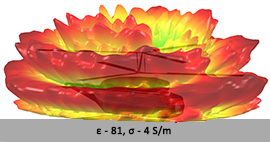
Real Ground Support with Sommerfeld Approach
New version of the program supports real ground modeling approach where the influence of the real ground is considered in rigorous formulation using Sommerfeld integrals.
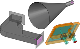
Waveguide Ports Support
EMCoS Studio 2019 supports definition of waveguide ports with pre-defined shapes (circular, coaxial and rectangular). These ports are considered in full wave analysis as waveguide cross-sections to which the excitation energy is applied.
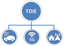
New Time Domain Integral Equation (TDIE) Solver
- Covers wide frequency range in a single simulation run
- Based on object surface discretization only without voluminous meshing
- Doesn’t require discretization of the entire computational domain
- Handles antennas represented as NF source or NF pattern calculated in frequency domain
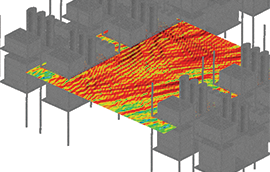
High Frequency Solution with New HF3D Solver
EMCoS Studio 2019 provides new HF3D solver for solution of high frequency problems in EM Simulation analysis type.
New EMCoS CAD Engine for Complex Geometry Processing
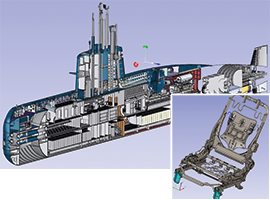
EMCoS CAD Engine is a new speed-oriented program for large CAD files handling and processing.
New Features and Improvements in Geometry and Model Handling Operations
- Export/import all program settings, user-defined shortcuts and project variables
- Improved functionality of exporting bodies with corresponding groups
- Copy/paste geometry objects from one project to another
- Attaching additional documents to materials stored in library
- Wire frame visualization handling for mesh objects
- Support impressed currents visualization as line segments to speed up model rendering in Viewer 3D
- Possibility to define toroidal windings with non-uniform turns distribution
- New option to set rotation center on mouse double-click
- Lock selection mode in 3D Viewer (Visibility and Pick Mode toolbar)
- Full screen mode support (View > Full Screen, F11)
- Support Zoom In operation using mouse right button and Shift key
- Possibility to highlight corresponding groups for geometry objects (bodies, meshes)
- Geometry accuracy setting control for TriD task (Low/Normal/High)
- Total Power specification in mW/dBm/dbW (in Manual mode)
- Show/Hide/All Except Selected commands are now available for Tasks
- Total number of frequency points for octave and decade ranges
New Features and Improvements in System Simulation Analysis Type
- Support of switching-off resistors for time domain burnout simulation of complex resistive networks
- Optimization for very large scale problems (possibility to handle hundreds of millions of elements in circuit model)
- Definition of default options for circuit solvers
- Support visualization of Network Parameters data for circuit elements
- Support of unit symbols (MEG, m, n, etc.) definition in Assign Circuit dialog
- Multi selection of pins for several schematic devices
- Better handling of hybrid cables in System Diagram
New Features and Improvements in EMCoS SimDAT
- Touchstone data conversion to mixed-mode S-parameters
- New Convolution with Signal Spectrum mode in FFTWerk
- Possibility to manage output files order in Outputs dialog
- Possibility to view 2D results for several AFS outputs
- Near Field 3D Distribution visualization on near field probes
- Extension of Near Field 3D Distribution for near field areas based on wire segments
- Controlling of impressed currents visualization mode (Normal and Lite)
- Possibility to change curves order on a plot directly from Tree View using drag-and-drop
- Possibility to change curve data Y offset for linear plots
- Legend settings control (text color and font) separately for each curve
- Extension of default appearance settings for curves, eye pattern and differential markers
- Advanced plot data export considering user-defined limits
- Advanced plot export to various image file formats (*.bmp, *.png, *.jpeg, *.emf, *.svg, *.pdf)
- Improved icons for high resolution display
- Extension of EMScript with new output reading functions for all analysis types

